
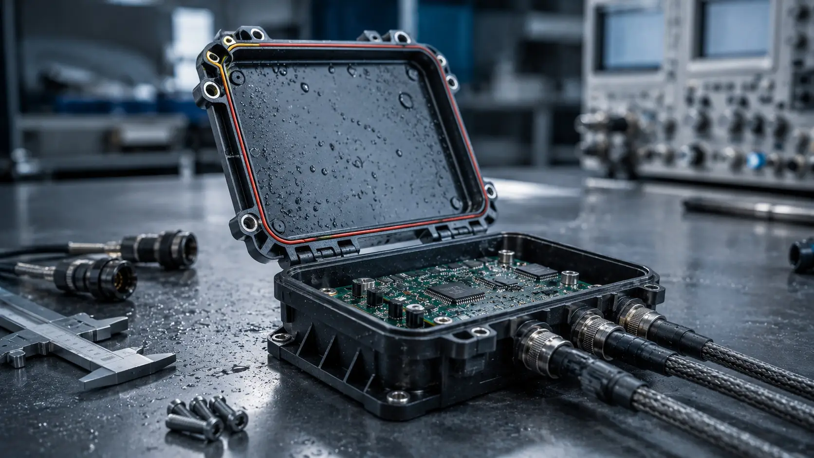
Electronic systems used in automotive applications, agricultural machinery and industrial equipment are rarely protected by the controlled conditions of an office or laboratory. They may be exposed to moisture, dust, vibration, temperature fluctuations, chemicals, pressure washing and continuous mechanical stress.
In these environments, the PCB enclosure is much more than a box around the electronics. It becomes an essential part of the reliability of the complete electronic control module.
Choosing the right PCB enclosure therefore requires more than matching the dimensions of a printed circuit board to a housing. Engineers must consider environmental protection, mechanical loads, thermal behaviour, connectivity, PCB integration, installation requirements and future production needs.
This guide explains the most important factors to consider when selecting a PCB enclosure for harsh environments.
What Is a PCB Enclosure?
A PCB enclosure is a housing designed to protect a printed circuit board and the electronic components mounted on it.
Depending on the application, the enclosure may provide protection against:
-
Water and moisture
-
Dust and dirt
-
Mechanical impact
-
Shock and vibration
-
Chemicals and industrial fluids
-
Temperature fluctuations
-
Electromagnetic interference
-
Accidental contact with electronic components
For demanding industrial, automotive and agricultural applications, the enclosure often also forms the mechanical interface between the PCB, electrical connectors, cable assembly and equipment in which the electronic module is installed.
For this reason, enclosure selection should be considered early in the electronic design process rather than after the PCB layout has already been completed.
Engineers looking for available configurations can also explore the ModICE enclosure range as a starting point for the mechanical design.
Start With the Operating Environment
The first question should not be:
Which enclosure fits my PCB?
It should be:
What does the electronic module need to survive?
Understanding the operating environment defines many of the requirements that follow.
Consider where the module will be installed and which environmental conditions it will experience during its complete service life.
Moisture and water
Electronics installed outdoors, inside vehicles or on machinery can be exposed to rain, condensation, splashing water or high-pressure cleaning.
Even small amounts of moisture entering an enclosure can cause corrosion, electrical leakage or permanent PCB failure.
The required sealing level therefore depends heavily on the application.
Dust and contamination
Agricultural and industrial environments can contain significant amounts of:
-
Dust
-
Sand
-
Soil
-
Metal particles
-
Oil
-
Grease
-
Fertiliser residue
-
Cleaning chemicals
An enclosure must prevent contaminants from reaching sensitive PCB components while remaining reliable throughout repeated temperature and pressure cycles.
Temperature
Electronic modules can experience considerable temperature changes.
An enclosure installed inside industrial equipment may operate continuously near heat-generating components, while electronics in vehicles or agricultural machinery can experience both very low and very high ambient temperatures.
The enclosure material, sealing system, PCB components and thermal design should therefore be evaluated as a complete system.
If the operating environment is still being defined, the ModICE overview of markets and applications provides useful context for different application types.
Determine the Required IP Protection
One of the most important specifications for a rugged electronic enclosure is its Ingress Protection rating, usually referred to as the IP rating.
The IP rating describes the degree of protection against solids and liquids.
However, selecting an enclosure purely because it has a high IP rating is not enough.
The actual application should determine the required protection.
For example, an electronic control module mounted inside a protected vehicle cabin faces very different conditions from a control unit mounted underneath agricultural machinery that is regularly pressure washed.
When evaluating ingress protection, consider:
-
Exposure to rain or spray
-
Temporary water immersion
-
High-pressure cleaning
-
Dust concentration
-
Mud and soil
-
Connector sealing
-
Pressure changes inside the enclosure
-
Installation orientation
The complete electronic module must remain protected, including the enclosure, connectors, seals and cable interfaces.
A high enclosure rating cannot compensate for an incorrectly sealed connector or poorly designed interface.
Consider Shock and Vibration
Vibration is often underestimated during enclosure selection.
Electronic modules installed on tractors, construction equipment, industrial machinery and vehicles can experience continuous vibration throughout thousands of operating hours.
Sudden mechanical shocks can create even higher loads.
These forces affect more than the enclosure itself. They can also influence:
-
PCB mounting points
-
Solder joints
-
Connectors
-
Heavy PCB components
-
Cable strain
-
Seals
-
Enclosure mounting points
A rugged PCB enclosure should support the PCB securely and prevent unnecessary movement.
The complete design should distribute mechanical loads rather than allowing stress to concentrate around individual screws, connectors or PCB mounting points.
For high-vibration applications, engineers should also consider the relationship between the cable harness and the enclosure. A heavy or poorly supported harness can transfer additional mechanical loads directly into the connector interface.
For projects where the enclosure and harness need to be developed as one system, ModICE also provides custom cable assembly solutions.
Match the Enclosure to the PCB
The dimensions of the PCB obviously play an important role, but simply finding an enclosure that is larger than the board is not sufficient.
Engineers should consider the complete three-dimensional PCB layout.
Important factors include:
-
PCB length and width
-
PCB thickness
-
Component height
-
Connector position
-
Mounting locations
-
Component keep-out areas
-
Clearance around heatsinks
-
Cable routing
-
Service access
Ideally, the PCB and enclosure should be developed together.
Selecting the enclosure early allows the PCB layout engineer to position connectors, mounting holes and high components around the mechanical limitations of the housing.
This can prevent expensive PCB redesigns later in the development process.
The available ModICE enclosure and header configurations can help engineers evaluate suitable mechanical starting points before finalising the PCB layout.
Determine Your I/O Requirements
For an electronic control module, connectivity is just as important as enclosure size.
Start by determining how many electrical connections the system requires.
Consider:
-
Power
-
Ground
-
Sensor inputs
-
Digital inputs
-
Analogue signals
-
Outputs
-
Communication buses
-
Diagnostic connections
-
RF connections
-
Future expansion
Do not only consider the number of connections needed for the first prototype.
If future product versions could require additional sensors or functions, allowing some additional I/O capacity may reduce the need for a complete enclosure and PCB redesign.
A modular enclosure system can be particularly valuable here because different header configurations can allow the same general enclosure concept to support multiple product variants.
Select the Right Connector Interface
The connector is one of the most critical areas of any sealed electronic enclosure.
It must provide reliable electrical connections while maintaining environmental sealing and resisting vibration.
Connector selection should consider:
-
Number of positions
-
Current requirements
-
Wire size
-
Signal type
-
Environmental sealing
-
Mating connector availability
-
Harness design
-
Mechanical retention
-
Serviceability
For production applications, connector availability is also an important supply-chain consideration.
Choosing a technically suitable but difficult-to-source connector can create unnecessary production risks later.
The enclosure, PCB header and external cable harness should therefore be treated as one interconnected system.
Evaluate Thermal Management
Sealing electronics against the environment creates another engineering challenge:
Heat has difficulty escaping from a sealed enclosure.
Electronic components such as processors, power electronics, regulators and drivers generate heat during operation.
If this heat cannot be transferred effectively to the environment, the internal temperature of the enclosure can rise significantly above ambient temperature.
Possible thermal-management strategies include:
-
Optimising PCB component placement
-
Conducting heat through the PCB
-
Using the enclosure as part of the thermal path
-
Integrated heatsinks
-
Thermal interface materials
-
Reducing internal power dissipation
-
Selecting suitable enclosure materials
Thermal analysis becomes increasingly important as electronic control modules become smaller while processing power and electrical loads increase.
The enclosure should therefore not be selected independently from the thermal design of the electronics.
Consider Pressure Equalisation and Condensation
A completely sealed enclosure can still experience internal pressure changes.
When temperature rises, the air inside the enclosure expands. When the enclosure cools, the internal pressure decreases.
Repeated temperature cycles can place stress on seals and potentially encourage moisture to enter through weak points.
Depending on the application, a breather vent can help equalise pressure while maintaining environmental protection.
Pressure management is especially relevant for equipment exposed to:
-
Outdoor temperature cycles
-
Rapid heating and cooling
-
Altitude changes
-
Sunlight
-
Engine heat
-
High-humidity environments
Condensation should also be considered.
Even when external water cannot directly enter the housing, changes in temperature and humidity can create moisture inside an electronic module under certain conditions.
Environmental protection therefore requires more than simply making an enclosure as airtight as possible.
Take EMI and EMC Into Account
Electronic control modules often operate close to motors, power cables, relays, radios, inverters and other sources of electromagnetic interference.
At the same time, the module itself must often meet electromagnetic compatibility requirements.
The enclosure and connector system can influence EMC performance through:
-
Grounding strategy
-
PCB layout
-
Cable routing
-
Connector selection
-
Filtering
-
Shielding
-
Ferrite components
-
RF connections
These requirements should be considered early.
Trying to solve an EMC problem after the PCB, connector and enclosure have already been finalised can result in significant redesign costs.
For applications with demanding electromagnetic requirements, available filtering and connector options should therefore be part of the enclosure-selection process.
Think Beyond the Prototype
The enclosure selected for a prototype must eventually work in production.
That means engineers and purchasing teams should consider more than technical performance.
Important commercial factors include:
-
Availability
-
Minimum order quantities
-
Lead times
-
Tooling requirements
-
Assembly time
-
Number of components
-
Supply continuity
-
Product variants
-
Future production volumes
A fully custom enclosure may provide complete design freedom, but it can also require substantial tooling investment and longer development times.
A modular enclosure platform can offer another approach.
By combining existing enclosure sizes, header configurations and accessories, engineers can create an application-specific electronic module without developing every mechanical component from scratch.
This can reduce development risk and make the transition from prototype to recurring production easier.
Once a project moves into recurring production, stock solutions such as Just-in-Time delivery, Vendor Managed Inventory and call-off arrangements can also help reduce inventory requirements and support predictable availability.
Consider Assembly and Serviceability
An enclosure should not only protect electronics after installation. It should also support efficient manufacturing and servicing.
Ask practical questions such as:
-
How is the PCB installed?
-
How many assembly steps are required?
-
Can the enclosure be opened when necessary?
-
Can the PCB be removed without damaging the housing?
-
How is the cable harness connected?
-
Are special assembly tools required?
-
Can the enclosure be tested before final installation?
Small improvements in assembly time can become important when production volumes increase.
Designing for assembly from the beginning can therefore reduce manufacturing costs and prevent unnecessary production complexity.
A Practical PCB Enclosure Selection Checklist
Before selecting a PCB enclosure, define at least the following requirements:
PCB
-
PCB dimensions
-
PCB thickness
-
Maximum component height
-
Mounting positions
Environment
-
Operating temperature
-
Exposure to water
-
Dust exposure
-
Chemicals and fluids
-
UV exposure
Mechanical
-
Vibration level
-
Shock requirements
-
Mounting method
-
Available installation space
Electrical
-
Required I/O count
-
Current requirements
-
Signal types
-
Communication interfaces
-
EMC requirements
-
RF requirements
Thermal
-
Power dissipation
-
Heat-generating components
-
Required heatsink
-
Ventilation or pressure equalisation
Production
-
Prototype quantity
-
Expected annual volume
-
Required delivery schedule
-
Assembly requirements
-
Long-term availability
Defining these parameters before selecting the enclosure significantly reduces the risk of redesign later.
Modular PCB Enclosures for Demanding Applications
ModICE modular PCB enclosures are designed for electronic control applications where environmental protection, flexibility and reliable connectivity are important.
Different enclosure sizes and header configurations make it possible to adapt the system to a range of PCB dimensions and I/O requirements.
Depending on the configuration and product family, solutions can incorporate features such as connector headers, ferrite filtering, RF interfaces, breather options and thermal-management features.
This modular approach makes ModICE suitable for applications across areas such as:
-
Off-highway vehicles
-
Electronic control modules
-
Sensor and communication systems
Rather than treating the enclosure as the final component around a finished PCB, engineers can select the enclosure, PCB header and cable interface together as part of the complete electronic system.
Need Help Selecting the Right PCB Enclosure?
Choosing the right enclosure requires balancing mechanical, environmental, electrical and commercial requirements.
If you are developing a new electronic control module, the ModICE technical team can help evaluate the most appropriate enclosure and connection configuration for your application.
To speed up the selection process, provide:
-
Your PCB dimensions
-
Required number of I/O connections
-
Operating environment
-
Temperature requirements
-
Sealing requirements
-
Expected production volumes
-
Any EMC, RF or thermal requirements
With this information, the technical team can help identify a suitable starting configuration and determine whether additional cable assembly or supply-chain support is required.
Request a quote for your PCB enclosure project or contact the ModICE technical team to discuss your application.